
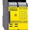

Mô đun AES 3075 24 VDC
Thông số kỹ thuật module an toàn Schmersal AES 3075 24 VDC
đại lý schmersal | đại lý AES 3075 24 VDC
nhà phân phối schmersal | nhà phân phối AES 3075 24 VDC
- Monitoring of BNS range magnetic safety sensors
- 2 safety contacts, STOP 0
- 4 Signalling outputs
Dữ liệu đặt hàng
| Note (Delivery capacity) |
Not available! |
| Mô tả loại sản phẩm |
AES 3075 24 VDC |
| Article number (order number) |
101138576 |
| EAN (European Article Number) |
4030661281360 |
| eCl@ss number, version 12.0 |
27-37-18-19 |
| eCl@ss number, version 11.0 |
27-37-18-19 |
| eCl@ss number, version 9.0 |
27-37-18-19 |
| ETIM number, version 7.0 |
EC001449 |
| ETIM number, version 6.0 |
EC001449 |
Phê duyệt – Tiêu chuẩn
| Certificates |
BG cULus |
Dữ liệu chung
| Tiêu chuẩn |
BG-GS-ET-14 BG-GS-ET-20 EN IEC 62061 EN ISO 13849-1 EN IEC 60947-5-1 EN IEC 60947-5-3 EN IEC 60947-5-5 EN IEC 60204-1 EN IEC 60947-1 |
| Vật liệu thân |
Glass-fibre, reinforced thermoplastic |
| Trọng lượng thô |
379 g |
Dữ liệu chung – Features
| Stop-Category |
0 |
| Wire breakage detection |
Yes |
| Cross-circuit detection |
Yes |
| Start input |
Yes |
| Feedback circuit |
Yes |
| Automatic reset function |
Yes |
| Integral system diagnostics, status |
Yes |
| Number of LEDs |
1 |
| Số lượng thường đóng (NC) |
4 |
| Số lượng thường mở (NO) |
4 |
| Number of undelayed semi-conductor outputs with signaling function |
4 |
| Number of safety contacts |
2 |
| Number of signalling outputs |
4 |
| Safety classification |
| Tiêu chuẩn |
EN ISO 13849-1 EN IEC 61508 |
| Safety classification – Relay outputs |
| Performance Level, up to |
d |
| Category |
3 |
| PFH value |
1.00 x 10⁻⁷ /h |
| Notice |
for max. 50,000 switching cycles/year and max. 80% contact load |
| Safety Integrity Level (SIL), suitable for applications in |
2 |
| Mission time |
20 Year(s) |
Dữ liệu cơ học
| Gắn |
Snaps onto standard DIN rail to EN 60715 |
Dữ liệu cơ học – Connection technique
| Kết thúc |
Screw terminals M20 x 1.5 |
| Cable section, maximum |
4 mm² |
| Note (Cable section) |
All indications including the conductor ferrules. |
| Tightening torque of Clips |
0.4 Nm |
Dữ liệu cơ học – Dimensions
| Width |
75 mm |
| Height |
100 mm |
| Depth |
110 mm |
Điều kiện môi trường xung quanh
| Mức độ bảo vệ of the enclosure |
IP40 |
| Mức độ bảo vệ of the mounting space |
IP54 |
| Mức độ bảo vệ of clips or terminals |
IP20 |
| Nhiệt độ môi trường |
+0 … +55 °C |
| Nhiệt độ bảo quản và vận chuyển, tối thiểu |
-25 °C |
| Nhiệt độ bảo quản và vận chuyển, tối đa |
+70 °C |
| Khả năng chống rung |
10…55 Hz, Amplitude 0.35 mm, ± 15 % |
| Khả năng chống sốc |
30 g / 11 ms |
Điều kiện môi trường xung quanh – Insulation values
| Điện áp chịu xung định mức Uimp |
0.5 kV |
| Danh mục quá áp |
III |
| Mức độ ô nhiễm |
2 |
Dữ liệu điện
| Frequency range |
50 Hz 60 Hz |
| Điện áp hoạt động |
24 VAC -15 % / +10 % |
| Ripple voltage |
10 % |
| Kiểm tra nhiệt hiện tại |
4 A |
| Điện áp hoạt động định mức |
24 VAC |
| Điện áp hoạt động định mức |
24 VDC |
| Rated AC voltage for controls, 50 Hz, minimum |
20.4 VAC |
| Rated control voltage at AC 50 Hz, maximum |
26.4 VAC |
| Rated AC voltage for controls, 60 Hz, minimum |
20.4 VAC |
| Rated control voltage at AC 60 Hz, maximum |
26.4 VAC |
| Rated AC voltage for controls at DC minimum |
20.4 VDC |
| Rated control voltage at DC, maximum |
28.8 VDC |
| Electrical power consumption |
8 W |
| Contact resistance, maximum |
0.1 Ω |
| Note (Contact resistance) |
in new state |
| Drop-out delay in case of power failure, typically |
80 ms |
| Drop-out delay in case of emergency, typically |
20 ms |
| Pull-in delay at automatic start, maximum, typically |
100 ms |
| Pull-in delay at RESET, typically |
20 ms |
Dữ liệu điện – Safe relay outputs
| Voltage, Loại sử dụng AC-15 |
230 VAC |
| Current, Loại sử dụng AC-15 |
6 A |
| Voltage, Loại sử dụng DC-13 |
24 VDC |
| Current, Loại sử dụng DC-13 |
6 A |
| Switching capacity, minimum |
10 VDC |
| Switching capacity, minimum |
10 mA |
| Switching capacity, maximum |
250 VAC |
| Switching capacity, maximum |
8 A |
Dữ liệu điện – Digital inputs
| Input signal, HIGH Signal “1” |
10 … 30 VDC |
| Input signal, LOW Signal “0” |
0 … 2 VDC |
| Conduction resistance, maximum |
40 Ω |
Dữ liệu điện – Digital Output
| Voltage, Loại sử dụng DC-12 |
24 VDC |
| Current, Loại sử dụng DC-12 |
0.1 A |
Dữ liệu điện – Relay outputs (auxiliary contacts)
| Switching capacity, maximum |
24 VDC |
| Switching capacity, maximum |
2 A |
Dữ liệu điện – Electromagnetic compatibility (EMC)
| EMC rating |
EMC-Directive |
Integral system diagnosis (ISD)
| Note (ISD -Faults) |
The following faults are registered by the safety monitoring modules and indicated by ISD. |
| Faults |
Failure of door contacts to open or close Cross-wire or short-circuit monitoring of the switch connections Interruption of the switch connections Fault on the input circuits or the relay control circuits of the safety monitoring module |
Other data
| Note (applications) |
Safety sensor Guard system |
Note
| Note (General) |
Inductive loads (e.g. contactors, relays, etc.) are to be suppressed by means of a suitable circuit. |
Wiring example
| Note (Wiring diagram) |
The wiring diagram is shown with guard doors closed and in de-energised condition. The ISD tables (Intergral System Diagnostics) for analysis of the fault indications and their causes are shown in the appendix. Start push button: A start push button (NO) can optionally be connected into the feedback circuit. With the guard door closed, the enabling paths are then not closed until the start push button has been operated. The feedback circuit monitors the position of the positive-guided NC contacts of the contactors K3 and K4. To secure 4 guard doors up to PL d and Category 3 Monitoring 4 guard door(s), each with a magnetic safety sensor of the BNS range The NC contacts of the external contactors must be wired in series to X1 (+) and X2. If less than 4 switches are connected, the unused terminals S21/S22 must be bridged before a NC contact is connected. This applies to the position of the jumpers in the safety-monitoring module with NC/NO configuration. The switch (H6) connected to terminals X3 and X4 switches the enabling outputs Y14 and Y24 on and off with the guard door closed. If no switch is connected, a jumper connection must be mounted between the terminals X3 and X4. |
Sản phẩm tương tự
Cảm biến
Cảm biến

Cảm biến
Cảm biến
Cảm biến

Cảm biến
Cảm biến

Cảm biến