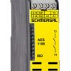

Mô đun AES 1136-2185
Thông số kỹ thuật module an toàn Schmersal AES 1136-2185
đại lý schmersal | đại lý AES 1136-2185
nhà phân phối schmersal | nhà phân phối AES 1136-2185
- Monitoring of BNS range magnetic safety sensors
- 1 safety contact, STOP 0
- 2 Signalling outputs
Dữ liệu đặt hàng
| Note (Delivery capacity) |
Not available! |
| Mô tả loại sản phẩm |
AES 1136-2185 |
| Article number (order number) |
101172221 |
| EAN (European Article Number) |
4030661300450 |
| eCl@ss number, version 12.0 |
27-37-18-19 |
| eCl@ss number, version 11.0 |
27-37-18-19 |
| eCl@ss number, version 9.0 |
27-37-18-19 |
| ETIM number, version 7.0 |
EC001449 |
| ETIM number, version 6.0 |
EC001449 |
| Available until |
31.12.2023 |
Phê duyệt – Tiêu chuẩn
| Certificates |
cULus |
Dữ liệu chung
| Tiêu chuẩn |
BG-GS-ET-14 BG-GS-ET-20 EN IEC 62061 EN ISO 13849-1 EN IEC 60947-5-1 EN IEC 60947-5-3 EN IEC 60947-5-5 EN IEC 60204-1 EN IEC 60947-1 |
| Climatic stress |
EN 60068-2-3 BG-GS-ET-14 |
| Vật liệu thân |
Glass-fibre reinforced thermoplastic, ventilated |
| Trọng lượng thô |
190 g |
Dữ liệu chung – Features
| Stop-Category |
0 |
| Wire breakage detection |
Yes |
| Cross-circuit detection |
Yes |
| Automatic reset function |
Yes |
| Start-up test |
Yes |
| Earth connection detection |
Yes |
| Integral system diagnostics, status |
Yes |
| Number of LEDs |
1 |
| Số lượng thường đóng (NC) |
2 |
| Số lượng thường mở (NO) |
1 |
| Number of undelayed semi-conductor outputs with signaling function |
2 |
| Number of safety contacts |
1 |
| Number of signalling outputs |
2 |
| Safety classification |
| Tiêu chuẩn |
EN ISO 13849-1 EN IEC 61508 |
| Safety classification – Relay outputs |
| Performance Level, up to |
d |
| Category |
3 |
| PFH value |
1.00 x 10⁻⁷ /h |
| Safety Integrity Level (SIL), suitable for applications in |
2 |
| Mission time |
20 Year(s) |
Dữ liệu cơ học
| Tuổi thọ cơ học, tối thiểu |
20,000,000 Operations |
| Gắn |
Snaps onto standard DIN rail to EN 60715 |
Dữ liệu cơ học – Connection technique
| Terminal designations |
IEC/EN 60947-1 |
| Kết thúc |
rigid or flexible Screw terminals M20 x 1.5 |
| Cable section, minimum |
0.25 mm² |
| Cable section, maximum |
2.5 mm² |
| Tightening torque of Clips |
0.6 Nm |
Dữ liệu cơ học – Dimensions
| Width |
22.5 mm |
| Height |
100 mm |
| Depth |
121 mm |
Điều kiện môi trường xung quanh
| Mức độ bảo vệ of the enclosure |
IP40 |
| Mức độ bảo vệ of the mounting space |
IP54 |
| Mức độ bảo vệ of clips or terminals |
IP20 |
| Nhiệt độ môi trường |
+0 … +55 °C |
| Nhiệt độ bảo quản và vận chuyển, tối thiểu |
-25 °C |
| Nhiệt độ bảo quản và vận chuyển, tối đa |
+70 °C |
| Khả năng chống rung |
10…55 Hz, Amplitude 0.35 mm, ± 15 % |
| Khả năng chống sốc |
30 g / 11 ms |
Điều kiện môi trường xung quanh – Insulation values
| Điện áp chịu xung định mức Uimp |
4 kV |
| Danh mục quá áp |
III |
| Mức độ ô nhiễm |
2 |
Dữ liệu điện
| Frequency range |
50 Hz 60 Hz |
| Điện áp hoạt động |
24 VAC -15 % / +10 % |
| Ripple voltage |
10 % |
| Kiểm tra nhiệt hiện tại |
6 A |
| Điện áp hoạt động định mức |
24 VAC |
| Điện áp hoạt động định mức |
24 VDC |
| Rated AC voltage for controls, 50 Hz, minimum |
20.4 VAC |
| Rated control voltage at AC 50 Hz, maximum |
26.4 VAC |
| Rated AC voltage for controls, 60 Hz, minimum |
20.4 VAC |
| Rated control voltage at AC 60 Hz, maximum |
26.4 VAC |
| Rated AC voltage for controls at DC minimum |
20.4 VDC |
| Rated control voltage at DC, maximum |
28.8 VDC |
| Electrical power consumption |
5 W |
| Contact resistance, maximum |
0.1 Ω |
| Note (Contact resistance) |
in new state |
| Drop-out delay in case of power failure, typically |
80 ms |
| Drop-out delay in case of emergency, typically |
20 ms |
| Pull-in delay at automatic start, maximum, typically |
100 ms |
| Pull-in delay at RESET, typically |
20 ms |
| Vật liệu tiếp điểm, điện |
Ag-Ni 10 and 0.2 µm gold-plated |
Dữ liệu điện – Safe relay outputs
| Voltage, Loại sử dụng AC-15 |
230 VAC |
| Current, Loại sử dụng AC-15 |
6 A |
| Voltage, Loại sử dụng DC-13 |
24 VDC |
| Current, Loại sử dụng DC-13 |
6 A |
| Switching capacity, minimum |
10 VDC |
| Switching capacity, minimum |
10 mA |
| Switching capacity, maximum |
250 VAC |
| Switching capacity, maximum |
8 A |
Dữ liệu điện – Digital inputs
| Input signal, HIGH Signal “1” |
10 … 30 VDC |
| Input signal, LOW Signal “0” |
0 … 2 VDC |
| Conduction resistance, maximum |
40 Ω |
Dữ liệu điện – Digital Output
| Voltage, Loại sử dụng DC-12 |
24 VDC |
| Current, Loại sử dụng DC-12 |
0.1 A |
Dữ liệu điện – Relay outputs (auxiliary contacts)
| Switching capacity, maximum |
24 VDC |
| Switching capacity, maximum |
2 A |
Dữ liệu điện – Electromagnetic compatibility (EMC)
| EMC rating |
EMC-Directive |
Integral system diagnosis (ISD)
| Note (ISD -Faults) |
The following faults are registered by the safety monitoring modules and indicated by ISD. |
| Faults |
Failure of the safety relay to pull-in or drop-out Failure of door contacts to open or close Cross-wire or short-circuit monitoring of the switch connections Interruption of the switch connections Fault on the input circuits or the relay control circuits of the safety monitoring module |
Other data
| Note (applications) |
Safety sensor Guard system |
Note
| Note (General) |
Inductive loads (e.g. contactors, relays, etc.) are to be suppressed by means of a suitable circuit. |
Wiring example
| Note (Wiring diagram) |
The wiring diagram is shown with guard doors closed and in de-energised condition. To secure a guard door up to PL d and Category 3 Monitoring 1 guard door(s), each with a magnetic safety sensor of the BNS range If one or two external relays or contactors are used to switch the load, the system can then only be classified in Category 3 to EN ISO 13849-1, if exclusion of the fault “Failure of the external contactors” can be substantiated and is documented, e.g. by using reliable down-rated contactors. A second contactor leads to an increase in the level of security by redundant switching to switch the load off. Modification for 2 NC contacts: The safety monitoring module can be modified to monitor two NC contacts by bridging the terminals A1 and X1. In this configuration, the short-circuit detection becomes inoperative. Expansion of enable delay time: The enable delay time can be increased from 0.1 s to 1.0 s by changing the position of a jumper link connection under the cover of the unit. The ISD tables (Intergral System Diagnostics) for analysis of the fault indications and their causes are shown in the appendix. |
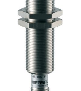
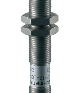
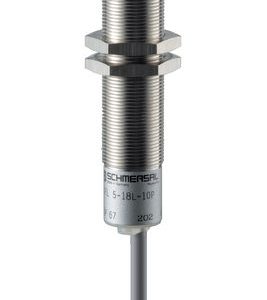
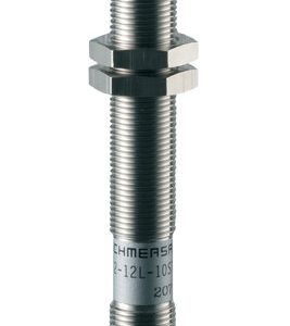
Sản phẩm tương tự
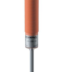
Cảm biến

Cảm biến
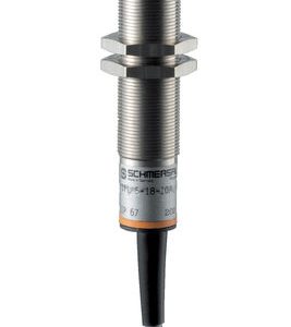
Cảm biến
Cảm biến
Cảm biến

Cảm biến
Cảm biến
Cảm biến